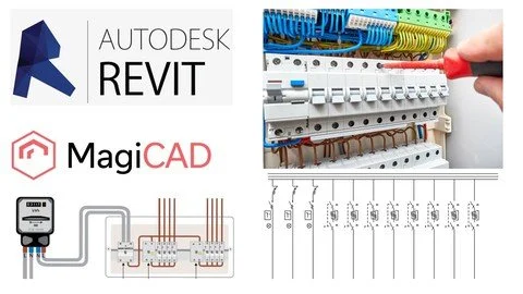
Switchboard Schematics And Single Line Diagrams In Revit
Manage Schematics in Revit with MagiCad Electrical. Course for dummies.
What you'll learn
When you complete this course you will have the skills and knowledge to use MagiCad for Revit to create switchboard schematic drawings.
You will understand how to use and set: Panelboard, Distribution System in Revit, Electrical Connector, Alternative voltage definition in Revit etc.
You will learn how to use Revit and MagiCad Electrical for creating Electrical Circuits.
You will get familiar with Panel Schedule.

Requirements
Revit
Basic knowledge about electrical engineering.
Description
In this course, you will learn how to create switchboard schematic drawings into a Revit project with MagiCAD.Also, this course starts from the basic and you will get familiar to the workflow to create and set properties for electrical circuits. Using MagiCad will be able to new features in Revit which will give you new possibilities beside those from Revit.
Here are the main topics from the course. Please follow them in the order even if sometimes few of them are well known.Alternative voltage definition in Revit.Electrical Connector. Explained all its parameters.Panel board. Distribution System in Revit.Demonstration_Revit_Sample_Project.Sample_Project_MagiCad.
Length of the circuits in Revit. Length between elements of the electrical circuit Wire Type Management.You will learn how to create electrical circuits, distribution system, voltages etc.You will understand how to correctly configure Revit settings for electrical systems.You will get familiar with different types of parameters: family, project or shared parameters.
The user should have a basic background about electrical engineering and basic about Revit. Also, using MagiCad you can add labels to your schematics like:Apparent load phase A;Apparent load phase B;Apparent load phase C;Power Factor;Apparent current;True load;Apparent load;Number of Elements;Number of Poles;Load Name;Circuit Number;Voltage Drop;MC Longest Branch Length;MC Min L-G Short-Circuit Current;Others.
Overview
Section 1: Introduction
Lecture 1 Introduction
Lecture 2 Alternative voltage definition in Revit.
Lecture 3 Electrical Connector.
Lecture 4 Panelboard. Distribution System in Revit.
Lecture 5 Demonstration_Revit_Sample_Project.
Lecture 6 Sample_Project_MagiCad
Lecture 7 Length of the circuits in Revit.
Section 2: MagiCad for Revit
Lecture 8 Switchboard schematics / Single line diagrams. Introduction.
Lecture 9 MagiCad_Sample_Project
Lecture 10 Revit_MagiCad_Sample_Project
Revit users,MagiCad Users,MEP Consultants. REVIT/BIM Electrical Modeler,Engineers.
Published 8/2022
MP4 | Video: h264, 1280x720 | Audio: AAC, 44.1 KHz
Language: English | Size: 1.09 GB | Duration: 2h 7m
Download
*
Manage Schematics in Revit with MagiCad Electrical. Course for dummies.
What you'll learn
When you complete this course you will have the skills and knowledge to use MagiCad for Revit to create switchboard schematic drawings.
You will understand how to use and set: Panelboard, Distribution System in Revit, Electrical Connector, Alternative voltage definition in Revit etc.
You will learn how to use Revit and MagiCad Electrical for creating Electrical Circuits.
You will get familiar with Panel Schedule.

Requirements
Revit
Basic knowledge about electrical engineering.
Description
In this course, you will learn how to create switchboard schematic drawings into a Revit project with MagiCAD.Also, this course starts from the basic and you will get familiar to the workflow to create and set properties for electrical circuits. Using MagiCad will be able to new features in Revit which will give you new possibilities beside those from Revit.
Here are the main topics from the course. Please follow them in the order even if sometimes few of them are well known.Alternative voltage definition in Revit.Electrical Connector. Explained all its parameters.Panel board. Distribution System in Revit.Demonstration_Revit_Sample_Project.Sample_Project_MagiCad.
Length of the circuits in Revit. Length between elements of the electrical circuit Wire Type Management.You will learn how to create electrical circuits, distribution system, voltages etc.You will understand how to correctly configure Revit settings for electrical systems.You will get familiar with different types of parameters: family, project or shared parameters.
The user should have a basic background about electrical engineering and basic about Revit. Also, using MagiCad you can add labels to your schematics like:Apparent load phase A;Apparent load phase B;Apparent load phase C;Power Factor;Apparent current;True load;Apparent load;Number of Elements;Number of Poles;Load Name;Circuit Number;Voltage Drop;MC Longest Branch Length;MC Min L-G Short-Circuit Current;Others.
Overview
Section 1: Introduction
Lecture 1 Introduction
Lecture 2 Alternative voltage definition in Revit.
Lecture 3 Electrical Connector.
Lecture 4 Panelboard. Distribution System in Revit.
Lecture 5 Demonstration_Revit_Sample_Project.
Lecture 6 Sample_Project_MagiCad
Lecture 7 Length of the circuits in Revit.
Section 2: MagiCad for Revit
Lecture 8 Switchboard schematics / Single line diagrams. Introduction.
Lecture 9 MagiCad_Sample_Project
Lecture 10 Revit_MagiCad_Sample_Project
Revit users,MagiCad Users,MEP Consultants. REVIT/BIM Electrical Modeler,Engineers.
Published 8/2022
MP4 | Video: h264, 1280x720 | Audio: AAC, 44.1 KHz
Language: English | Size: 1.09 GB | Duration: 2h 7m
Download
*