Engineering Resource
Analysis and Design of Telecommunication Tower
Introduction
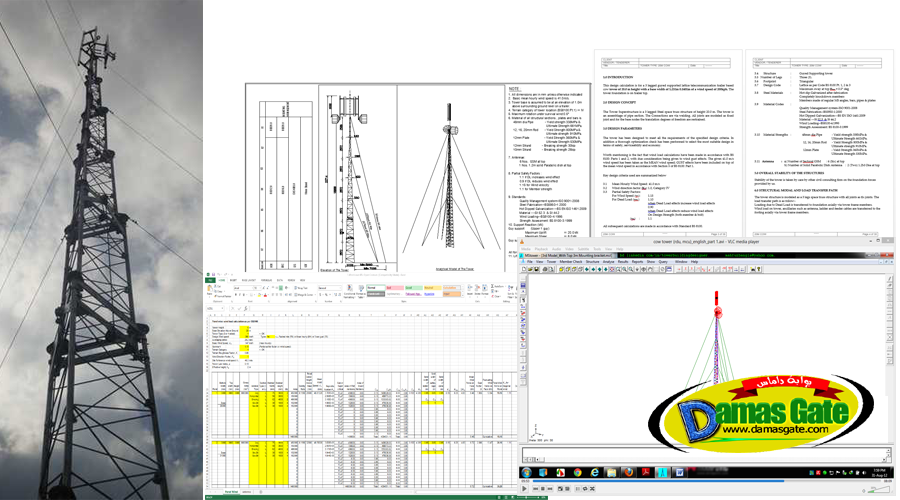
This design calculation is for a 3 legged guyed supported lattice telecommunication trailer based cow tower of 20.0 m height with a base width of 1.23±m 0.140±m of a wind speed of 200kph. The tower foundation is on trailer top.
Basic Concepts of Design of Telecommunication Tower
The Tower Superstructure is a 3 legged Steel space truss structure of height 20.0 m. The tower is an assemblage of pipe section. The Connections are via welding. All joints are modeled as fixed joint and for the base nodes the translation degrees of freedom are restrained.
Design Parameters
The tower has been designed to meet all the requirements of the specified design criteria. In addition a thorough optimization check has been performed to select the most suitable design in terms of safety, serviceability and economy.
Worth mentioning is the fact that wind load calculations have been made in accordance with BS 8100: Parts 1 and 2, with due consideration being given to wind gust effects. The given 41.0 m/s wind speed has been taken as the MEAN wind speed; GUST effects have been included on top of the mean wind speed in accordance with Section 5 of BS 8100: Part 1.
Over All Stability of the Structure
Stability of the tower is taken by care by other civil consulting firm on the foundation forces provided by us.
Loading and Load Transfer Paths
The tower structure is modeled as a 3 legs space truss structure with all joints as fix joints. The load transfer path is as follow:-
Loading due to Dead Load is transferred to foundation axially via tower frame members.
Wind load on tower, ancillaries such as antenna, ladder and feeder cables are transferred to the footing axially via tower frame members.
Analysis
The modeling and analysis are done using customize software called MS Tower V 6.0. The model assembly file is as shown in the TD file attached in the analysis output. The analysis of the tower for the various loads and loads combinations for members design and tower rotation and deflection check under operational conditions are in the attached TWR file in the analysis output.
Content
Design Report
Specifications
MS Tower Model files
Relevant Spreadsheets
AutoCAD Drawings
Design and Construction Review (Video Lecture)
635MB
Download
*